Smart Shapes are represented by an instance the NSmartShape class. There is an instance of the NShapeSheet class associated with each smart shape, which can be obtained from the Sheet property of the NSmartShape class.
| C# |
Copy Code
|
// create a smart shape and get its sheet
NSmartShape shape = new NSmartShape();
NShapeSheet sheet = shape.Sheet;
|
| Visual Basic |
Copy Code
|
' create a smart shape and get its sheet
Dim shape As New NSmartShape()
Dim sheet As NShapeSheet = shape.Sheet
|
One Dimensional and Two Dimensional Shapes
A shape can be either one dimensional (1D) or two dimensional (2D). You can choose whether to create a 1D or 2D shape, based on the way in which the user (or the program that uses the smart shape) needs to interact with it:
-
1D shapes behave like a line. They have start and end points, which you can modify. The start and end points are exposed by the StartPoint and EndPoint properties. Use them only if the shape is a 1D shape.
-
2D shapes behave like a box. You can change the 2D shape width, height, angle of rotation and pin point. These aspects of 2D shapes are exposed by the Width, Height, Angle, PinPoint and LocalPinPoint properties.
Whether the shape is 1D or 2D is determined by the IsOneDimensional property. This property checks whether the underlying shape sheet has an End-Points Section (see End Points Section for more information).
Coordinate Systems
The content of a shape (in most cases the shape geometry) is defined in the shape local coordinate system. The origin of this system is the (0, 0) point, which is located in the Top-Left corner of the box defined by the shape Width and Height. In the shape local coordinate system X coordinates increase to the right, and Y coordinates increase to the bottom.
The parent coordinate system is the coordinate system of the shape host. In case the smart shape resides in a group, this is the local coordinate system of the group. In case that the smart shape is displayed on a device this is the device coordinate system.
The transformation, which converts local coordinates to parent coordinates is defined by the Transform Section of the shape sheet (see Transform Section for more information). You can easily obtain this transformation via the Transform property of the NSmartShape class.
The following image illustrates the coordinate systems in the case of a group, which hosts a single cross shape:
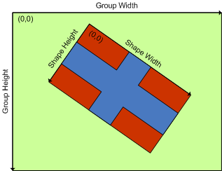
The green area represents the coordinate system of the group. The red area represents the shape local coordinate system.
Shape Appearance
As you would expect the appearance of smart shapes is defined by instances of the Nevron Graphics Appearance Styles (see Appearance Styles for more information).
The filling of the shape is specified by the FillStyle property. The outline of the shape is specified by the StrokeStyle property. The shape shadow is specified by ShadowStyle property.
All these properties accept a null value. When one of these properties is set to null the shape tries to inherit the respective style from the group in which the shape resides. If the shape does not reside in a group, it will be displayed without the respective appearance (i.e. filling, outline or shadow).
To obtain the actual style, with which the shape will be displayed you can use the ComposeFillStyle, ComposeStrokeStyle and ComposeShadowStyle methods.
Background Image
Optionally there can be a background image displayed behind the geometry of each smart shape. This image is a bitmap, which is specified by the BackgroundImage property. If this property is set to null, the shape will be displayed without a background image. By default this property is set to null.
Control Points
Each smart shape can have control points, which can be used for the visual editing of the shape. The control points are defined by the Controls Section of the shape sheet (see Controls Section for more information).
The NSmartShape class provides several methods and properties, which facilitate the most common operations with control points. The count of control points can be obtained from the ControlsCount property. You can get and set the location of a control point via the GetControlPoint and SetControlPoint methods. To determine the control point visibility you can use the GetControlVisible method. To get the control point tooltip you can use the GetControlTooltip method.
Painting Smart Shapes
Smart shapes are designed to support double pass rendering. That is why there are two methods, which you can use to display a smart shape on a Nevron Graphics Device - PaintAppearance and PaintShadow.
The PaintAppearance method accepts a reference to a device, which implements the IN2DDevice interface. It renders the shape filling and outline.
The PaintShadow method accepts a reference to a device, which implements the IN2DShadowDevice interface. It renders the shape shadow.