The following image illustrates the structural organization of the drawing document:
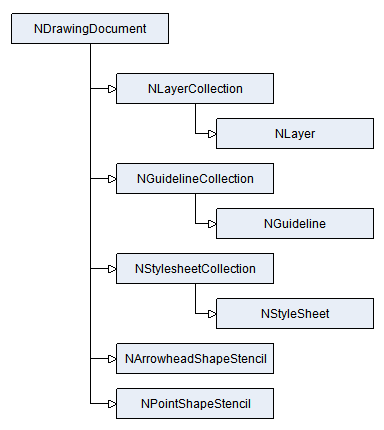
Drawing documents (or simply drawings) are represented by the NDrawingDocument class, which derives from NDocument. This is the most widely used type of document, since it can host an interactive drawing. Drawing documents are components, which appear in the Visual Studio toolbox. They are represented by the following toolbox item:

In the context of WinForms drawing documents are displayed and edited with the help of a WinForm NDrawingView instance(s). In the context of WebForms drawing documents are displayed with the help of a WebForm NDrawingView instance(s).
The following image illustrates the structural organization of the drawing document:
The content of each drawing is divided in layers. The layers of a drawing are contained in a NLayerCollection instance, accessible from the Layers property. Of all layers in a drawing only one can be active at a time. The active layer is obtained from the ActiveLayer property and is specified by the ActiveLayerUniqueId property. By default each drawing is created with only one layer, which is at the same time the active layer.
The following code adds a new layer to a drawing document and makes it the currently active one:
| C# |
Copy Code
|
|---|---|
// create a new layer and make it the active one NLayer layer = new NLayer(); drawing.Layers.AddChild(layer); drawing.Layers.ActiveLayerUniqueId = layer.UniqueId; |
|
| Visual Basic |
Copy Code
|
|---|---|
' create a new layer and make it the active one Dim layer As New NLayer drawing.Layers.AddChild(layer) drawing.Layers.ActiveLayerUniqueId = layer.UniqueId |
|
Typically you will add shapes to the active layer. For example:
| C# |
Copy Code
|
|---|---|
// add a rectangle shape to the active layer drawing.ActiveLayer.AddChild(new NRectangleShape(0, 0, 100, 100); |
|
| Visual Basic |
Copy Code
|
|---|---|
' add a rectangle shape to the active layer drawing.ActiveLayer.AddChild(New NRectangleShape(0, 0, 100, 100)) |
|
Guidelines are infinite lines, which help you better align and reposition the content of a drawing. Currently there are two types of guidelines - horizontal and vertical - represented by the NHorizontalGuideline and NVerticalGuideline classes respectively. They both derive from the base NGuideline abstract class. The guidelines of a drawing are contained in an instance of the NGuidelineCollection class, an instance of which can be obtained from the Guidelines property.
The following code adds a horizontal and a vertical guideline to a drawing document:
| C# |
Copy Code
|
|---|---|
// create a horizontal guideline with Y coordinate 20 (in scene units) NHorizontalGuideline hguide = new NHorizontalGuideline(20); drawing.Guidelines.AddChild(hguide); // create a vertical guideline with X coordinate 30 (in scene units) NVerticalGuideline vguide = new NVerticalGuideline(20); drawing.Guidelines.AddChild(vguide); |
|
| Visual Basic |
Copy Code
|
|---|---|
' create a horizontal guideline with Y coordinate 20 (in scene units) Dim hguide As New NHorizontalGuideline(30) drawing.Guidelines.AddChild(hguide) ' create a vertical guideline with X coordinate 30 (in scene units) Dim vguide As New NVerticalGuideline(30) drawing.Guidelines.AddChild(vguide) |
|
The content of a drawing is measured in logical measurement units. The logical measurement unit is controlled by the MeasurementUnit property. The measurement unit in which the content is painted is called world measurement unit. In case there is no drawing scale the world measurement unit is equal to the logical measurement unit. This is the most common case.
Some applications however require to display either too small or too large scenes, which are impossible to visualize without a drawing scale. You must have a large monitor to display a room of 3x3 meters and there is no monitor, which can display something measured in kilometers. In these cases you must use a drawing scale.
Drawing scale is a user defined ratio between the logical measurement unit and the world measurement unit. For example 1 meter = 1 mm is a commonly used Metric drawing scale. The ratio can however not be 1:1 - you can for example specify: 1 meter = 2 mm.
Drawing scale helps you work with the document content as if it is measured with the real world measurement unit that you want to use. For example: a room can be defined as a rectangle with width 3 and height 3 meters in logical measurement units. If the 1 meter = 2 mm drawing scale is applied, on the screen it will be represented by a rectangle with width 6 mm and height 6 mm. In case there is no drawing scale the world measurement unit is equal to the logical measurement unit.
The following code example applies a drawing scale in which 1 meter = 1 mm:
| C# |
Copy Code
|
|---|---|
drawing.MeasurementUnit = NMetricUnit.Meter; drawing.DrawingScaleMode = DrawingScaleMode.CustomScale; drawing.CustomWorldMeasurementUnit = NMetricUnit.Millimeter; drawing.CustomScale = 1; |
|
| Visual Basic |
Copy Code
|
|---|---|
drawing.MeasurementUnit = NMetricUnit.Meter drawing.DrawingScaleMode = DrawingScaleMode.CustomScale drawing.CustomWorldMeasurementUnit = NMetricUnit.Millimeter drawing.CustomScale = 1 |
|
Drawings have bounds, which are accessible from the Bounds property. The bounds of the drawing are measured in the logical measurement unit. The drawing bounds can be calculated in several modes:
The current bounds mode is controlled by the AutoBoundsMode property.
In case the mode is set to AutoInflateToContent or AutoSizeToContent, the drawing will take into account the AutoBoundsPadding property (controls the padding applied to the computed bounds) and the AutoBoundsMinSize property (controls the minimal size of automatic bounds).
In case the mode is set to CustomNonConstrained or CustomConstrained you can manually resize the drawing by invoking the SizeToContent or InflateToContent methods.
The Z-order of the shadows displayed by the elements in a drawing is controlled by the ShadowsZOrder property (accepts values from the ShadowsZOrder enumeration). Currently you can specify one of the following values:
Drawings have the following set of additional attributes:
By default drawings add an instance of the NDrawingDataObjectAdaptor class to their DataObjectAdaptors collection. This type of adaptor can adapt data objects of the following formats: