This topic explains the coordinates systems used in the Nevron Diagram for .NET product.
A coordinate system in 2D space can be defined by any set of two non colinear vectors (axes). The coordinate system is in this way a system for specifying points using coordinates measured in some specified way along the system axes. The most important 2D coordinate systems are:
-
Cartesian Coordinate System - this is the simplest 2D coordinate system, which consists of coordinate axes oriented perpendicularly to each other.
A transformation, which transforms a Cartesian coordinate system C1 to a coordinate system C2 is said to be a Cartesian Transform, if the C2 coordinate system is again a Cartesian coordinate system. Such transformation will preserve the orthogonality of vectors perpendicular to the coordinate system axes.
Cartesian transformations are particularly useful in diagramming, since an axes perpendicular rectangle will again remain a rectangle after it has been transformed. Cartesian transformations are invertible. Microsoft Visio for example uses only Cartesian transformations.
In Nevron Diagram for .NET models and drawings are defined in Cartesian coordinates, but are transformed with affine transformations (see below). Models inside aggregates can however be instructed to use Cartesian scale (e.g. scaled in such a way that they preserve orthogonality of axes colinear vectors).
-
Affine Coordinate System - this is a more complex coordinate system defined by two non colinear axes (not necessarily perpendicular to each other) . An Affine Transform is any transformation, which converts coordinates from one affine coordinate system to another.
Nevron Diagram for .NET uses only invertible affine transformations. Affine transformations unlike Cartesian transformations provide you with better transformation abilities.
A common design pattern for almost all commercial graphics applications is to use hierarchical coordinate systems. In a hierarchy of transformable elements there are three coordinate systems in which you can specify coordinates:
- Model - the model coordinate system is the system of measure of some element content, which is not affected by the transformations applied to it.
In Nevron Diagram for .NET models are defined in the model coordinate system.
-
Parent - since elements can be hierarchically transformed, the parent coordinate system is the model coordinate system of the element parent. The transformation, which transforms an element to the model coordinate system of its parent is called Local Transformation. The parent coordinate system is a relative coordinate system, since the parent on its turn can be transformed to its parent and so on.
In Nevron Diagram for .NET each model has a transformation, which converts its model (local) coordinates to the model coordinate system of its aggregate model.
-
Scene - the scene coordinate system is a logical coordinate system, which defines the absolute position of the elements inside a scene. The transformation, which transforms an element to the scene coordinate system is called Scene Transformation. The scene coordinate system is measured in measurement units appropriate for the specific application (for example a floor plan can be measured in meters).
In Nevron Diagram for .NET drawings are defined in the scene coordinate system, which is measured with a logical measurement unit.
Following is an example of hierarchical transformations:
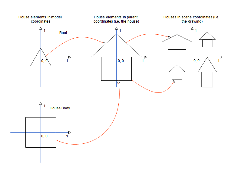
In this example the house elements (Roof and Body) are defined in model coordinates. They are then transformed with a local transformation to the coordinate system of the house (in this example both elements have been scaled and translated). The house on its turn can be transformed in different ways to the scene coordinate system.
In the GDI+ coordinate systems, X coordinates increase to the right, and Y coordinates increase to the bottom. GDI+ in general uses three coordinate systems:
-
World - the world coordinate system in the coordinate system in which rendering takes place. For example when you call some drawing method of the Graphics class it assumes that all coordinates and measures are specified in the world coordinate system.
In Nevron Diagram for .NET the measurements of all styles are specified in the world coordinate system. Drawing documents use a special transformation, which maps scene coordinate to world coordinates. This transformation is generally used for drawing scale, but can also be used for any type of scaling, which must not scale style measurements (see below).
-
Page - world coordinates are transformed to page coordinates with the help of a world transformation, which is held in the Transform property of the Graphics class. You should know that this transformation transform not only world coordinates, but the specified measures of all pens, brushes etc. For example a line drawn with a pen width 1 in world coordinates will appear twice thicker, if the world transformation scales the X and Y coordinates twice.
In Nevron Diagram for .NET this transformation is used by views to provide native panning and zooming of drawing documents. The GDI+ Page Coordinate System is in this documentation also referred as View Coordinate System.
-
Device - the device coordinate system is the system of measure of the output device (e.g. monitor, printer etc.). Page coordinates are transformed to device coordinates with the help of a page transformation. The purpose of the page transformation is to provide you with native support for different measurement units, that is why the page transformation is only exposed by two property of the Graphics class - PageUnit and PageScale.
In Nevron Diagram for .NET the page transformation is indirectly specified by the drawing world measurement unit.