Diagram for .NET / Getting Started / Integrating in Windows Forms / My First WinForm Diagram

My First WinForm Diagram

The following guide will help you create a WinForm application, which displays the following diagram:

 Create a new WinForm application
  1. Open Microsoft Visual Studio for .NET
  2. Select the the File - New - Project command - the new project dialog will be displayed
  3. Select Visual C# Projects - Windows Applications
  4. Click the OK button - the designer for Form1 should automatically appear

 Insert diagram components and controls
  1. The installation must register the NDrawingDocument component and NDrawingView control in the Nevron Diagram WinForm toolbox group. In case this group is created go to step 7.
  2. Right click on the Toolbox background. Select the "Add/Remove Items..." command.
  3. In the "Customize Toolbox" dialog select the ".NET Framework Components" tab.
  4. Click on the "Browse..." button and select the Nevron.Diagram.dll assembly located in the installation directory.
  5. The NDrawingDocument component should appear at the end of the toolbox Windows Forms list.
  6. Perform the same actions once again, but this time select the Nevron.Diagram.WinForm.dll assembly. As a result the  NDrawingView control should appear at the end of the toolbox Windows Forms list.
  7. Open the solution explorer and add a reference to the Nevron.Diagram.Shapes.dll assembly.
  8. Drag and drop the NDrawingDocument to the form - it should appear in the component tray, since it is a component.
  9. Drag and drop the NDrawingView to the form and resize it as you see fit.
  10. Double click on Form1 to generate the Form1_Load method.
 Programmatically create the diagram

In the Form1_Load method copy and paste the following code:

C#
Copy Code
...
using Nevron.GraphicsCore;
using Nevron.Diagram;
using Nevron.Diagram.Shapes;
using Nevron.Diagram.WinForm;
...
private void Form1_Load(object sender, System.EventArgs e)
{
    // begin view init
    nDrawingView1.BeginInit();

    // display the document in the view
    nDrawingView1.Document = nDrawingDocument1;

    // do not show ports
    nDrawingView1.GlobalVisibility.ShowPorts = false; 

    // hide the grid
    nDrawingView1.Grid.Visible = false; 

    // fit the document in the viewport 
    nDrawingView1.ViewLayout = ViewLayout.Fit; 

    // apply padding to the document bounds
    nDrawingView1.DocumentPadding = new Nevron.Diagram.NMargins(10);

    // init document
    nDrawingDocument1.BeginInit();

    // create the flowcharting shapes factory
    NFlowChartingShapesFactory factory = new NFlowChartingShapesFactory(nDrawingDocument1);

    // modify the connectors style sheet
    NStyleSheet styleSheet = (nDrawingDocument1.StyleSheets.GetChildByName(NDR.NameConnectorsStyleSheet, -1) as NStyleSheet); 

    NTextStyle textStyle = new NTextStyle();
    textStyle.BackplaneStyle.Visible = true;
    textStyle.BackplaneStyle.StandardFrameStyle.InnerBorderWidth = new NLength(0); 
    styleSheet.Style.TextStyle = textStyle;

    styleSheet.Style.StrokeStyle = new NStrokeStyle(1, Color.Black);
    styleSheet.Style.StartArrowheadStyle.StrokeStyle = new NStrokeStyle(1, Color.Black);
    styleSheet.Style.EndArrowheadStyle.StrokeStyle = new NStrokeStyle(1, Color.Black);

    // create the begin shape 
    NShape begin = factory.CreateShape(FlowChartingShapes.Termination);
    begin.Bounds = new NRectangleF(100, 100, 100, 100);
    begin.Text = "BEGIN";
    nDrawingDocument1.ActiveLayer.AddChild(begin);

    // create the step1 shape
    NShape step1 = factory.CreateShape(FlowChartingShapes.Process);
    step1.Bounds = new NRectangleF(100, 400, 100, 100);
    step1.Text = "STEP1";
    nDrawingDocument1.ActiveLayer.AddChild(step1);

    // connect begin and step1 with bezier link
    NBezierCurveShape bezier = new NBezierCurveShape();
    bezier.StyleSheetName = NDR.NameConnectorsStyleSheet;
    bezier.Text = "BEZIER";
    bezier.FirstControlPoint = new NPointF(100, 300);
    bezier.SecondControlPoint = new NPointF(200, 300);
    nDrawingDocument1.ActiveLayer.AddChild(bezier);
    bezier.FromShape = begin;
    bezier.ToShape = step1;
        
    // create question1 shape
    NShape question1 = factory.CreateShape(FlowChartingShapes.Decision);
    question1.Bounds = new NRectangleF(300, 400, 100, 100);
    question1.Text = "QUESTION1";
    nDrawingDocument1.ActiveLayer.AddChild(question1);

    // connect step1 and question1 with line link
    NLineShape line = new NLineShape();
    line.StyleSheetName = NDR.NameConnectorsStyleSheet;
    line.Text = "LINE";
    nDrawingDocument1.ActiveLayer.AddChild(line);
    line.FromShape = step1;
    line.ToShape = question1;

    // create the step2 shape
    NShape step2 = factory.CreateShape(FlowChartingShapes.Process);
    step2.Bounds = new NRectangleF(500, 100, 100, 100);
    step2.Text = "STEP2";
    nDrawingDocument1.ActiveLayer.AddChild(step2);

    // connect step2 and question1 with HV link
    NStep2Connector hv1 = new NStep2Connector(false); 
    hv1.StyleSheetName = NDR.NameConnectorsStyleSheet;
    hv1.Text = "HV1";
    nDrawingDocument1.ActiveLayer.AddChild(hv1);
    hv1.FromShape = step2;
    hv1.ToShape = question1;

    // connect question1 and step2 and with HV link
    NStep2Connector hv2 = new NStep2Connector(false); 
    hv2.StyleSheetName = NDR.NameConnectorsStyleSheet;
    hv2.Text = "HV2";
    nDrawingDocument1.ActiveLayer.AddChild(hv2);
    hv2.FromShape = question1;
    hv2.ToShape = step2;

    // create a self loof as bezier on step2
    NBezierCurveShape selfLoop = new NBezierCurveShape();
    selfLoop.StyleSheetName = NDR.NameConnectorsStyleSheet;
    selfLoop.Text = "SELF LOOP";
    nDrawingDocument1.ActiveLayer.AddChild(selfLoop);
    selfLoop.FromShape = step2;
    selfLoop.ToShape = step2;
    selfLoop.Reflex(); 

    // create step3 shape
    NShape step3 = factory.CreateShape(FlowChartingShapes.Process);
    step3.Bounds = new NRectangleF(700, 600, 100, 100);
    step3.Text = "STEP3";
    nDrawingDocument1.ActiveLayer.AddChild(step3);

    // connect question1 and step3 with an HVH link
    NStep3Connector hvh1 = new NStep3Connector(false, 50, 0, true); 
    hvh1.StyleSheetName = NDR.NameConnectorsStyleSheet;
    hvh1.Text = "HVH1";
    nDrawingDocument1.ActiveLayer.AddChild(hvh1);
    hvh1.FromShape = question1;
    hvh1.ToShape = step3;

    // create end shape
    NShape end = factory.CreateShape(FlowChartingShapes.Termination);
    end.Bounds = new NRectangleF(300, 700, 100, 100);
    end.Text = "END";
    nDrawingDocument1.ActiveLayer.AddChild(end);

    // connect step3 and end with VH link
    NStep2Connector vh1 = new NStep2Connector(true); 
    vh1.StyleSheetName = NDR.NameConnectorsStyleSheet;
    vh1.Text = "VH1";
    nDrawingDocument1.ActiveLayer.AddChild(vh1);
    vh1.FromShape = step3;
    vh1.ToShape = end;

    // connect question1 and end with curve link (uses explicit ports)
    NRoutableConnector curve = new NRoutableConnector(RoutableConnectorType.DynamicCurve);
    curve.StyleSheetName = NDR.NameConnectorsStyleSheet;
    curve.Text = "CURVE";
    nDrawingDocument1.ActiveLayer.AddChild(curve);
    curve.StartPlug.Connect(question1.Ports.GetChildAt(3) as NPort);
    curve.EndPlug.Connect(end.Ports.GetChildAt(1) as NPort);
    curve.InsertPoint(1, new NPointF(500, 600));

    // set a shadow to the nDrawingDocument1. Since styles are inheritable all objects will reuse this shadow
    nDrawingDocument1.Style.ShadowStyle = new NShadowStyle(
        ShadowType.GaussianBlur,
        Color.Gray,
        new NPointL(5, 5),
        1,
        new NLength(3));

    // shadows must be displayed behind document content
    nDrawingDocument1.ShadowsZOrder = ShadowsZOrder.BehindDocument; 

    // end nDrawingDocument1 init
    nDrawingDocument1.EndInit();

    //end view init
    nDrawingView1.EndInit();
}
Visual Basic
Copy Code
...
Imports Nevron.GraphicsCore
Imports Nevron.Diagram
Imports Nevron.Diagram.Shapes
Imports Nevron.Diagram.WinForm
...
Private Sub Form1_Load(ByVal sender As System.Object, ByVal e As System.EventArgs) Handles MyBase.Load
    ' begin view init
    NDrawingView1.BeginInit()

    ' display the document in the view
    NDrawingView1.Document = NDrawingDocument1
        
    ' do not show the ports 
    NDrawingView1.GlobalVisibility.ShowPorts = False

    ' hide the grid
    NDrawingView1.Grid.Visible = False
        
    ' fit the document in the viewport
    NDrawingView1.ViewLayout = ViewLayout.Fit
        
    ' apply padding to the document bounds
    NDrawingView1.DocumentPadding = New Nevron.Diagram.NMargins(10)

    ' init document
    NDrawingDocument1.BeginInit()
                        
    ' create the flowcharting shapes factory
    Dim factory As NFlowChartingShapesFactory = New NFlowChartingShapesFactory(NDrawingDocument1)

    ' modify the connectors style sheet
    Dim styleSheet As NStyleSheet = NDrawingDocument1.StyleSheets.GetChildByName(NDR.NameConnectorsStyleSheet, -1)

    Dim textStyle As NTextStyle = New NTextStyle()
    textStyle.BackplaneStyle.Visible = True
    textStyle.BackplaneStyle.StandardFrameStyle.InnerBorderWidth = New NLength(0)
    styleSheet.Style.TextStyle = textStyle

    styleSheet.Style.StrokeStyle = New NStrokeStyle(1, Color.Black)
    styleSheet.Style.StartArrowheadStyle.StrokeStyle = New NStrokeStyle(1, Color.Black)
    styleSheet.Style.EndArrowheadStyle.StrokeStyle = New NStrokeStyle(1, Color.Black)

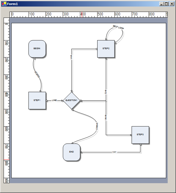
    ' create the begin shape 
    Dim begin As NShape = factory.CreateShape(FlowChartingShapes.Termination)
    begin.Bounds = New NRectangleF(100, 100, 100, 100)
    begin.Text = "BEGIN"
    NDrawingDocument1.ActiveLayer.AddChild(begin)

    ' create the step1 shape
    Dim step1 As NShape = factory.CreateShape(FlowChartingShapes.Process)
    step1.Bounds = New NRectangleF(100, 400, 100, 100)
    step1.Text = "STEP1"
    NDrawingDocument1.ActiveLayer.AddChild(step1)

    ' connect begin and step1 with bezier link
    Dim bezier As NBezierCurveShape = New NBezierCurveShape()
    bezier.StyleSheetName = NDR.NameConnectorsStyleSheet
    bezier.Text = "BEZIER"
    bezier.FirstControlPoint = New NPointF(100, 300)
    bezier.SecondControlPoint = New NPointF(200, 300)
    NDrawingDocument1.ActiveLayer.AddChild(bezier)
    bezier.FromShape = begin
    bezier.ToShape = step1

    ' create question1 shape
    Dim question1 As NShape = factory.CreateShape(FlowChartingShapes.Decision)
    question1.Bounds = New NRectangleF(300, 400, 100, 100)
    question1.Text = "QUESTION1"
    NDrawingDocument1.ActiveLayer.AddChild(question1)

    ' connect step1 and question1 with line link
    Dim line As NLineShape = New NLineShape()
    line.StyleSheetName = NDR.NameConnectorsStyleSheet
    line.Text = "LINE"
    NDrawingDocument1.ActiveLayer.AddChild(line)
    line.FromShape = step1
    line.ToShape = question1

    ' create the step2 shape
    Dim step2 As NShape = factory.CreateShape(FlowChartingShapes.Process)
    step2.Bounds = New NRectangleF(500, 100, 100, 100)
    step2.Text = "STEP2"
    NDrawingDocument1.ActiveLayer.AddChild(step2)

    ' connect step2 and question1 with HV link
    Dim hv1 As NStep2Connector = New NStep2Connector(False)
    hv1.StyleSheetName = NDR.NameConnectorsStyleSheet
    hv1.Text = "HV1"
    NDrawingDocument1.ActiveLayer.AddChild(hv1)
    hv1.FromShape = step2
    hv1.ToShape = question1

    ' connect question1 and step2 and with HV link
    Dim hv2 As NStep2Connector = New NStep2Connector(False)
    hv2.StyleSheetName = NDR.NameConnectorsStyleSheet
    hv2.Text = "HV2"
    NDrawingDocument1.ActiveLayer.AddChild(hv2)
    hv2.FromShape = question1
    hv2.ToShape = step2

    ' create a self loof as bezier on step2
    Dim selfLoop As NBezierCurveShape = New NBezierCurveShape()
    selfLoop.StyleSheetName = NDR.NameConnectorsStyleSheet
    selfLoop.Text = "SELF LOOP"
    NDrawingDocument1.ActiveLayer.AddChild(selfLoop)
    selfLoop.FromShape = step2
    selfLoop.ToShape = step2
    selfLoop.Reflex()

    ' create step3 shape
    Dim step3 As NShape = factory.CreateShape(FlowChartingShapes.Process)
    step3.Bounds = New NRectangleF(700, 600, 100, 100)
    step3.Text = "STEP3"
    NDrawingDocument1.ActiveLayer.AddChild(step3)

    ' connect question1 and step3 with an HVH link
    Dim hvh1 As NStep3Connector = New NStep3Connector(False, 50, 0, True)
    hvh1.StyleSheetName = NDR.NameConnectorsStyleSheet
    hvh1.Text = "HVH1"
    NDrawingDocument1.ActiveLayer.AddChild(hvh1)
    hvh1.FromShape = question1
    hvh1.ToShape = step3

    ' create end shape
    Dim [end] As NShape = factory.CreateShape(FlowChartingShapes.Termination)
    [end].Bounds = New NRectangleF(300, 700, 100, 100)
    [end].Text = "END"
    NDrawingDocument1.ActiveLayer.AddChild([end])

    ' connect step3 and end with VH link
    Dim vh1 As NStep2Connector = New NStep2Connector(True)
    vh1.StyleSheetName = NDR.NameConnectorsStyleSheet
    vh1.Text = "VH1"
    NDrawingDocument1.ActiveLayer.AddChild(vh1)
    vh1.FromShape = step3
    vh1.ToShape = [end]

    ' connect question1 and end with curve link (uses explicit ports)
    Dim curve As NRoutableConnector = New NRoutableConnector(RoutableConnectorType.DynamicCurve)
    curve.StyleSheetName = NDR.NameConnectorsStyleSheet
    curve.Text = "CURVE"
    NDrawingDocument1.ActiveLayer.AddChild(curve)
    curve.StartPlug.Connect(CType(IIf(TypeOf question1.Ports.GetChildAt(3) Is NPort, question1.Ports.GetChildAt(3), Nothing), NPort))
    curve.EndPlug.Connect(CType(IIf(TypeOf [end].Ports.GetChildAt(1) Is NPort, [end].Ports.GetChildAt(1), Nothing), NPort))
    curve.InsertPoint(1, New NPointF(500, 600))

    ' set a shadow to the document. Since styles are inheritable all objects will reuse this shadow
    NDrawingDocument1.Style.ShadowStyle = New NShadowStyle(ShadowType.GaussianBlur, Color.Gray, New NPointL(5, 5), 1, New NLength(3))

    ' shadows must be displayed behind document content
    NDrawingDocument1.ShadowsZOrder = ShadowsZOrder.BehindDocument
        
    ' end NDrawingDocument1 init
    NDrawingDocument1.EndInit()

    ' end view init
    NDrawingView1.EndInit()
End Sub