Force directed layout
In This Topic
Force directed algorithms use a physical analogy to arrange graphs. The force layout algorithms are encapsulated inside the
NForceDirectedLayout class (derived from
NLayout), which can be instanced on demand:
| C# |
Copy Code
|
// create a new force directed layout associated with the specified document
NForceDirectedLayout fdLayout = new NForceDirectedLayout(document);
|
| Visual Basic |
Copy Code
|
' create a new force directed layout associated with the specified document
Dim fdLayout As New NForceDirectedLayout(document)
|
Force directed layout concept
Force directed layouts view the graph as a system of bodies with forces acting between the bodies. The algorithm seeks a configuration of the bodies with locally minimum energy, that is a position for each body, such that the sum of the forces on each body is zero. Such configuration is called equilibrium configuration. Generally all force directed layouts are defined by two parts:
-
Model - a force system defined by the vertices and edges, which provides a physical model for the graph
-
Algorithm - the method used to find an equilibrium configuration for the defined system
The current implementation of NForceDirectedLayout is based on a model with spring and electrical forces acting upon the graph vertices. In this model edges between graph vertices represent springs connecting the vertices. Vertices are treated as equally charged particles, which repel each other. The force acting on each vertex v is:
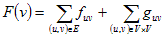
where:
- fuv - is the spring force between vertices u and v. This force follows Hooke's law, which means that it is proportional to the difference between the distance between u and v and the zero-energy length of the spring. The purpose of the spring force is to enforce the distance between two connected vertices to be equal to the spring length.
- guv - is the electrical repulsion between vertices u and v. This force follows an inverse square law. The purpose of the electrical force is to ensure that vertices are not too close together.
Springs model
The natural (zero energy) length of all springs can be controlled by the
SpringLength property. The spring stiffness is controlled by the
SpringStiffness property. The spring stiffness is a constant, which controls the tendency for the distance between two vertices connected with an edge to be closer to the spring length. It is possible to instruct the algorithm to use logarithmic springs instead of springs based on Hooke's law by setting the
LogarithmicSprings property to true.
Electrical model
The strength of the electrical repulsion between all vertices depends on the value of the
ElectricalRepulsion property. This setting is usually initialized with a large value, since the electrical repulsion decreases in an inverse square with the increase of the distance between vertices. A larger value for this property will make a more symmetrical drawing.
Force directed layout algorithm
An iterative algorithm is implemented, which tries to reach an equilibrium configuration in a finite number of iterations - controlled by the MaxIterations property.
You can choose whether the algorithm must randomize the vertex positions prior to its execution with the help of the RandomizePositions property.
On each iteration the algorithm computes the force acting on each vertex and each vertex is moved in the direction of that force by a small amount of it's force magnitude, controlled by the ForceMagnitudeFactor property.
The algorithm stops if it has performed the maximum number of iterations or all forces in the system are smaller than the value specified by the StopForce property - that is the system has reached an equilibrium approximation.
Preserve vertex positions
You can choose whether the algorithm must preserve the locations of the layout building nodes by settings the
PreserveNodesPositions property to true. For example suppose that you have a graph G and you have selected one node from it - node1. Passing only node1 to the force directed layout will apply a layout on the entire graph, but the node1 position will not be changed.
Related Examples
Windows Forms: Layouts - Force Directed Layout
See Also
Common layout features | NForceDirectedLayout
See Also